
This time I'm going to introduce the usage of a kind of magnetic sensors called digitalmagnetoresistive sensors. Magnetoresistive sensors are based on a property of several materials called magnetoresistance, consisting in the variation of their electrical resistivity when placed in a magnetic field. In practice, the current flow through a magnetoresistive wire depends on the strength and on the orientation of an external magnetic field. The adjective "digital" in the name of these sensors refers to the fact that they provide just two states: either they are sensing a magnetic field or they are not. In other words, they are not able to provide a precise and accurate measurement of the strength of any external magnetic field: they only react to magnetic fields stronger than a given threshold, providing a sort of signal that can be, in some cases, somewhat proportional to its strength. In most cases these devices are sensitive to the magnetic field only if it is oriented in a given direction (typically parallel to one of the sides of their package).
The Honeywell 2SS52M is a device that belongs to the class of digital magnetoresistive sensors. It comes in a compact package with three pins (see picture): two of which are used to bias it (GND and Vcc), 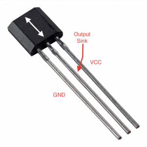 while the third one is its "output". The device is sensitive to magnetic fields oriented such that they are parallel to the longest side of its package (the white arrow in the figure). Being the sensor omnipolar, the orientation of the magnetic field doesn't matter: either south-north or north-south alignment triggers the device.
 while the third one is its "output". The device is sensitive to magnetic fields oriented such that they are parallel to the longest side of its package (the white arrow in the figure). Being the sensor omnipolar, the orientation of the magnetic field doesn't matter: either south-north or north-south alignment triggers the device.
When the external magnetic field in the given direction is strong enough, the device works as a sink for the current. There are, in fact, two kinds of sensors: those whose output mode is source and those whose output mode is sink. A source is a point from which current flows from the device; a sink, on the contrary, is a point to which current flows. In order to operate a sink sensor, you need an external power supply to be connected to the sink through a resistor. If no magnetic field is detected, the sink works as an open switch and current does not flow from the power supply to the device. When a magnetic field is measured, instead, the sink acts as a closed switch and some current flows from the external power supply to the device.
According to the Ohm's Law, when a current I flows through a resistor R, the voltage drop across it is V=RI. In order to tell if the device is sensing a magnetic field, it is enough to measure V: if it is zero, no external magnetic field is present (apart, of course, the earth's magnetic field); if a strong enough magnetic field is placed close to the sensor you should be able to measure a voltage V.

We can use an Arduino Uno board to build a device that is able to tell you when a magnet is close to a given position (see the schematic above). The 2SS52M can be operated with a wide variety of input voltages (from 3.8 V up to 30 V). Connecting its leftmost pin to the Arduino ground (black wire) and its rightmost pin to the Arduino 5V pin (red wire) is enough to make it working. Then, we can use the Arduino 3.3V pin as an external power supply: connecting this pin to the central pin of the sensor through a resistor chain will make some current flowing from Arduino to the device when a magnetic field is sensed. It is important to limit such a current that must not exceed the maximum current that the Arduino board can provide through its pins: 200 mA. We must then connect the 2SS52M central pin to the 3.3V Arduino pin by means of a resistor of at least
R = V/I = 3.3/0.2=16.5 Ω
Of course, since we do not need a large current flowing, using much higher values is recommended: this way the current flowing through the resistor will be much less, reducing power consumption and heating. For example, using a 2 kΩ resistor will cause a current of I = V/R = 3.3/2000=1.65 mA from Arduino to the sensor. On the other hand, the voltage drop across the resistor will still be 3.3V, independently of the current.
In the schema shown above we illustrate a possible alternative: the resistor through which the current flows from the Arduino to the sink is made by the series of two resistors. We then measure the voltage drop across one of them (we then expect that we are going to read 3.3/2=1.65 V). There is no special reason to do that, but to show how a voltage divider works!
The tricky part comes when trying to measure the voltage drop across the resistor. Voltages can be measured using the Arduino analog pins A0-A5. They measure a voltage up to 5 V with respect to the Arduino ground. However, the voltage drop across the resistor cannot be measured relative to it. Let's try to understand why. In the figure below you can see a schematic of our circuit.

The magnetic sensor is represented as a box connected to the ground and the 5V pin of the Arduino board. The sink is in fact a transistor that conducts when a magnet is close to the sensor and does not if the magnet is far from it. It is connected through a chain of resistors to the 3.3V Arduino pin. If you try to measure the voltage between the ground and the resistor lead connected to the Arduino pin you always see 3.3 V, irrespective of the presence of a magnet close to the sensor, since such a potential is always there with respect to ground.
If, however, you measure the voltage drop across the resistor, i.e. as shown in the picture below,
 you would see 0 V if no current is drawn from the 3.3 V pin to the sink, while you can measure 3.3 V in the opposite case. We must then measure the voltage difference between the leads of the resistors. To do that we can measure the potentials V0 and V1 at the two leads of the resistor with respect to the Arduino ground and obtain the voltage drop as V=V1-V0. We can, then, measure the voltage V0 connecting one lead of the resistor to the Arduino A0 pin (blue wire), and the voltage V1 connecting the other resistor lead to the Arduino A1 pin (orange wire).
When no current flows through the resistor the difference between the reading of A1 and A0 will be zero (or very small, because of possible fluctuations in the measurement). If the difference exceeds a given threshold, then, a current is flowing into the resistor, then an external magnetic field has been detected by the sensor.
This device can be used as a proximity sensor. Fix the 2SS52M to something and a small magnet (see, e.g., the small neodymium magnets in the picture) to something else: when the magnet is close enough to the sensor it gives you a signal. In the Arduino sketch you can tell when the magnetic field is sensed waiting for a voltage drop different from zero using a function like this:
void waitUntilSensed() {
  int j = 0;
  int thr = 100 + analogRead(A0); // get the "zero" level
  while (j < thr) {
    j = analogRead(A1); // read the other lead potential
  }
  return;
}
When entering into the function, the first operation is to measure the voltage at A0, that is expected to be the same of A1, using the analogRead() function We then just continuously read the A1 pin until its value exceeds those of A0 plus 100 (or any other large enough value). The function returns as soon as a magnetic field is detected.
With two such devices you can build a system with which you can measure the speed of a cart or of a falling object. Fix a small magnet to the cart and two 2SS52M sensors on a rail at a reasonable small distance x (e.g. 5 cm) with respect to each other.
With the Arduino connected to the sensors you can measure the times of passage of the cart in front of the first and the second sensor: t0 and t1. The time needed to the cart to travel for the corresponding distance x is t=t1-t0, then its average speed is v=x/t. Look at the following sketch.
// the sensor reading for which we can consider it as triggered
#define THRESHOLD 100
// the distance between sensors (in m)
#define S10 0.05

void sense(int pin, long int &t, long int &duration, float &resolution) {
/* This method return the time at which a magnetic field was sensed by a device read on pin*/
  int j = 0;
  int thr = THRESHOLD + analogRead(A0); // get the "zero" level
  while (j < thr) {
    j = analogRead(pin);
  }
  // get the time at which the signal starts rising
  long int lead = micros();
  while (j > thr) {
    j = analogRead(pin);
  }
  // get the time at which the signal fall down
  long int trail = micros();
  t = (trail + lead)/2;
  duration = trail - lead;
  resolution = duration/sqrt(12);
}

void loop() {
  // measures the times of passage
  int t0, w0, sigma0;
  int t1, w1, sigma1;
  sense(A1, t0, w0, sigma0);
  sense(A2, t1, w1, sigma1);
  double v = S10/(t1-t0);
  ...
}
The sense() method waits until a non-zero voltage is provided from the sensor connected to the given pin. The micros() function returns the number of microseconds elapsed since the beginning of the sketch. Then, the sense() method provides a measurement of the time at which a magnet passed in front of the corresponding sensor, the duration of the pulse and its error (given by the statistical theory as the width of the pulse divided by the square root of 12). The ampersand in front of the parameters in the function tells the compiler to pass the address of the memory to the function and not its value, such that the readings are all passed to the variables used in the loop() function.
In fact we measure the time at which the voltage between A0 and another pin becomes different from zero, then we wait until it becomes zero again (in the second while loop). Measuring the time at which the signal starts to be non zero and the one at which it returns to zero, we can assume that the magnet passed in front of the sensor at a time given by the average of the two times. The duration of the passage is given by the difference of the two times.
Measuring the times of passage in front of two sensors we are then able to tell the speed of the cart as the ration between the distance traveled S0 and the time of travle t1-t0. With three or more sensors, you can then measure the speed at various positions of an object to study its motion. With such a system you can do many physics experiments, in fact. The cost of such a system can be below 40 EUR, while a professional system to make the same experiments with a comparable precision may cost from hundreds to even thousands of euros!
According to my very preliminary tests, I was able to trigger the device using a small neodymium magnet (4 mm diameter) when it was at about 2-3 cm distance from the sensor. My plan is to make a systematic measurement campaign that will be reported on my free e-book on scientific uses of Arduino boards. The e-book is in preparation and there is a very preliminary version athttp://www.roma1.infn.it/people/organtini/publications/scientificArduino.pdf.
No comments:
Post a Comment